0-10V dimming and its application in street lighting
0-10V dimming and its application in street lighting
Introduction
The 0-10V topology is a common and popular control method in the entire lighting industry. It was originally developed for controlling fluorescent ballasts, hence the name “fluorescent dimming” or “5-wire dimming.” With the continuous growth of the LED market, it has become one of the most common control topologies in the LED industry. The 0-10V dimming system controls the brightness of lighting fixtures by using a 0-10V DC voltage signal. In this system, a 0V signal indicates that the fixture is off (sometimes it’s 1-10V, which means the lamps cannot be completely turned off), while a 10V signal represents full power operation of the fixture. By changing the voltage of the control signal, the lighting fixture can be dimmed or brightened. The International Electrotechnical Commission (IEC) has described 0-10V dimming in Appendix E of the IEC standard 60929, which is one of the reasons why this system is widely accepted and highly matured. Currently, it is embraced by the majority of electrical companies and engineers in the industry.
What’s 0-10V dimming?
0-10V dimming is a common method used to control the brightness of lighting fixtures, especially in LED lighting systems. It involves adjusting the light output by varying the voltage signal supplied to dimmable fixtures (equipped with 0-10V dimmable drivers) within the range of 0 to 10 volts (hence called “0-10V dimming”). The principle of 0-10V dimming is relatively simple: when the control signal is set to 0V, the lighting output dims or turns off completely, and as the control signal increases towards 10V, the brightness of the light increases proportionally.
Color of 0-10V dimming cables and their connections
Before 2021, the 0-10V control wiring was traditionally identified by purple and gray colors. However, starting from January 1, 2022, there was a modification that prohibited using gray color for control lines to avoid confusion with the gray neutral wire. To adapt to this change, 0-10V signal lines are now designated with purple and pink sheathed wires. As a result, the 0-10V control wiring may be either purple/pink or purple/gray. Below is the wiring diagram for the connection between the 0-10V dimming power supply and the controller:

0-10V control type(Sink or Source)
Sink Type: In a sink type 0-10V dimming system, the dimming control device (such as a dimmer or lighting controller) acts as a current sink. It connects to the lighting fixture’s dimming input and draws current from the 0-10V control circuit. By varying the amount of current drawn, the sink control device regulates the brightness of the fixture. In this configuration, the control device sinks current to control the dimming level.
Source Type: In a source type 0-10V dimming system, the dimming control device acts as a voltage source. It generates a variable voltage between 0V and 10V on the control circuit. The lighting fixture’s dimming input receives this voltage signal, and the fixture’s internal circuitry adjusts the brightness based on the voltage level. In this configuration, the control device provides the voltage source for controlling the dimming level.

Generally speaking, in a sinking System the control voltage is produced by the light(with 0-10V LED driver) and not by the controller. The light produces the voltage, typically 10 volts DC, which is then sent to a controller, which uses a resistor to ground the voltage. This grounding of the voltage allows the 10vdc to be lowered (grounding), which causes the voltage to go down to as low as 0 volts DC. In source system, 0-10 volt DC is produced by a controller which then sends the voltage to a light which is turned brighter or dimmer based upon the amount of voltage applied from the controller. Typically, 0 volts is off and the higher the voltage, the brighter the light becomes and the lower the voltage the dimmer the street light(for 0-10V streetlights) becomes.
How does 0-10V dimming work?
0-10V is a low-voltage dimming system. The dimming driver typically consists of two wires in the circuit. One is gray, representing the standard signal, and the other is purple, representing 10V. When these two wires are open and not in contact with each other (when 0-10V dimming is not applicable, the two wires remain unconnected), the signal will stay at 10V, and the light output will be at 100% level. When the wires are shorted or come into contact with each other, the dimming driver will set the brightness to the minimum value or 0V.
In simple terms, the controller/LED driver primarily operates based on voltage as a reference parameter. We can envision the controller as a water valve that can precisely control the flow of water through a pipe. The controller (dimmer) connected to the 0-10VDC driver pulls down or “sinks” the 10VDC to a lower voltage corresponding to the desired dimming level. For example, when a microwave sensor is set to 50% (the signal voltage drops to 5VDC), the connected driver reads this voltage on its signal input and responds by reducing the output (LED module) to the corresponding level, completing the entire dimming process.
How to use 0-10V dimming in street lighting?
0-10V dimming power supply is a common method used to control the brightness of lighting fixtures, enabling the adjustment of light intensity. In road lighting, this dimming power supply can be paired with various controllers. Firstly, microwave sensors automatically adjust the brightness of road lighting based on occupancy, achieving energy efficiency and energy-saving goals. Secondly, controllers installed on NEMA bases of streetlights enable remote dimming, facilitating real-time adjustments of the lighting effect. Additionally, this system allows centralized control and intelligent management. Moreover, light sensors and timers are sometimes used to transmit signals as 0-10V to achieve dimming in indoor lighting. In daylight applications, microwave sensors and control panels are more commonly used in 0-10V systems. These methods enable energy conservation and promote the sustainable development of urban lighting.
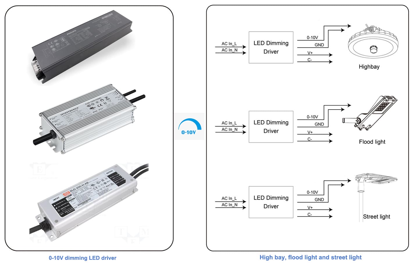
With motion sensor
Connect the microwave(motion) sensor to the 0-10V dimming power supply and configure the trigger conditions (detection range, delay time, and photosensitivity). When the microwave sensor detects motion, it sends a 10V signal to the power supply, causing the light fixtures to be at 100% brightness. If no motion is detected within a certain time, the controller will send a 5V (within the 0-10V range) signal to the LED driver, enabling dimming of the light fixtures with motion sensor. Microwave sensors are suitable for scenarios where automatic adjustment of street light fixture brightness based on motion detection is required.

With NEMA socket (e.g., Zigbee system)
Use a Zigbee smart control system to connect the central controller with individual light controllers. The central controller sends instructions to the individual light controllers, and the light controllers convert the instructions into 0-10V dimming signals, which are then transmitted to the power supply. Similar control systems include LoRa, but in this case, the power supply may choose Dali. Zigbee and LoRa are methods for remote and centralized adjustment of light fixture brightness through a smart control system. To achieve the final dimming of the fixtures, it is essential to ensure that the fixtures are equipped with LED drivers that support 0-10V or Dali dimming.
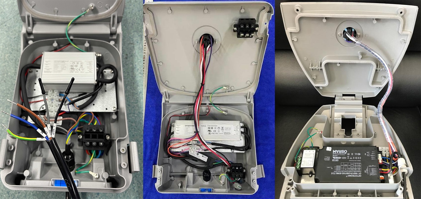
With daylight sensor/control panel (indoor lighting)
Use a standard 0-10V dimmer to connect the power supply and the light fixtures. The dimmer can change the output voltage by manual control or an external control signal, achieving dimming of the light fixtures. This method is suitable for indoor lighting fixtures that require manual or periodic dimming but may not be ideal for scenarios like street lighting that demand automatic or remote control. Similar to daylight sensor, street light with dimmable photocell needs 0-10V dimming LED driver. With this solution, the street light can automatically change the output as per ambient brightness.
ZGSM lighting solutions with 0-10V dimming
Summary
Despite the emergence of new control methods and technologies in the lighting industry, 0-10V dimming remains a reliable, cost-effective, and efficient way to adjust light fixture brightness. It has been in existence for a long time and is widely used in various applications. With the introduction of new technologies such as Dali, Bluetooth, and wireless control, lighting engineers and users have started paying attention to these alternatives. However, these new technologies may not always be well-suited for practical implementation, either due to their high cost or the immaturity of the solutions.
Currently, many dimming solutions still rely on 0-10V dimming. Many lighting companies continue to use it because it is a simple and reliable method to control light intensity, and it comes with relatively low costs. As we have seen in this article, 0-10V dimming finds numerous applications when combined with microwave sensors, NEMA bases, and other smart control systems. Understanding these applications can greatly assist in finding suitable lighting solutions for your needs. Stay in touch with us to get more details.
Rated Products
Related Blogs
Related Cases
People also ask
Author introduction

Hello Customers,
My name is Taylor Gong, I’m the product manager of ZGSM Tech. I have been in the LED lights industry for more than 13 years. Good at lighting design, street light system configuration, and bidding technology support. Feel free to contact us. I’m happy to provide you with the best service and products.
Email: [email protected] | WhatsApp: +8615068758483

