Lighting fixture manufacturing by ZGSM – SMT machine
Lighting fixture manufacturing by ZGSM – SMT machine
Introduction
The core technology of LED lights is LED, LED is short for light-emitting diode. An LED is a semiconductor device that, in layman’s terms, emits light when current flows through it. The principle is that when the diode passes forward current, a small number of electrons are sent from p→n, and a small number of holes are sent from n→p. Holes and electrons flow from the electrodes to the p-n junction under different electrode voltages. At the junction boundary, holes and electrons meet and recombine, and the electrons drop to lower energy levels while releasing energy in the form of photons. When current is passed through the LED, the electrons and holes recombine, emitting light in the process. LEDs allow current to flow forward and block current flow in the reverse direction.
Knowing the principle, we will give a detailed introduction to some main parameters of LED, precautions for use, and some knowledge of SMT placement machine in actual production in this article. We hope everyone can have a deeper understanding of LEDs and the application of LEDs in lighting fixture manufacturing.

LED manufacturing process
The LED light manufacturing process is a complex process consisting of three main steps: LED chip, LED package and LED lamp. Every step must be performed to the highest standards to ensure quality control and product consistency.
1. First, the semiconductor material is grown in a high-pressure, high-temperature chamber, where the elements (gallium, arsenic, phosphorus) are purified, mixed and liquefied into a concentrated solution. Once combined, place a stick in the solution and pull slowly. After the rod is removed, the solution cools rapidly and begins to crystallize, forming long boules.
2. Next, the boule is cut into semiconductor wafers, and each wafer is ground and cleaned to remove any dust, dirt, or organic material.
3. Doping treatment: adding dopants to the crystal layer to form p-type and n-type regions to form a p-n junction.
4. LED structure preparation: Deposit a series of semiconductor material layers in the p-n junction to form multiple quantum well active layers, and prepare metal leads and other contact layers at the same time.
5. Processing and packaging: The LED chip is processed by cutting, patching, etc., and then packaged in a suitable package, usually a plastic or metal package with a reflective lampshade or lens.
6. Esting and quality control: Various testing and quality control steps are carried out, including testing of parameters such as luminous flux, spectrum, color coordinates, brightness, etc., to ensure that the LED lights fixture meets the performance requirements.
Efficiency of LED chips
LEDs are widely used because of their high luminous efficiency. In the manufacture of semiconductor products, the performance variation around the average value given in the manufacturer’s technical data sheet. Therefore, manufacturers classify LED components by their luminous flux (efficiency), chromaticity, peak or dominant wavelength, and forward voltage. ZGSM will choose LEDs with medium to high quality, and its light efficiency can generally reach about 170-180lm/w. When applied to LED lamps, its overall light efficiency can reach 140-150lm/W. This ensures that our product include street light, flood light, canopy light and others can outperform the competition.
CRI/CCT/MacAdam Ellipsis
CRI is a quantitative measure of the ability of a light source to faithfully reveal the color of various objects compared to natural or standard light sources. CRI has options like 70, 80, 90 etc.
CCT light sources typically emit light in a wide range of different wavelengths and are generally considered to have only one color. We call the color of this light source the correlated color temperature. It’s measured in the Kelvin unit and is most commonly found between 2200 Kelvin degrees and 6500 Kelvin degrees.
McAdam ellipse shows deviations in color. The ellipse was invented and named after scientist David McAdam. MacAdam’s measurements show that colors that deviate from the reference color can be represented by ellipses arranged around the initial value, rather than by perfect circles. A MacAdam ellipse is an area on the chromaticity diagram that encompasses everything from the color at the center of the ellipse to all colors indistinguishable by the average human eye. Usually there are 1 steps, 2 steps, 3 steps, 4 steps, 5 steps, 6 steps and 7 steps. Among them, 1-3 steps, the naked eye basically cannot identify the difference, 4-5 steps, the difference can be detected by the naked eye carefully, 6-7 steps, the difference is easier to be detected by the naked eye, usually the LEDs with 3-5 difference are selected for the street light project.

ESD(excessive voltage transients)
LEDs are very sensitive to excessive voltage transients (eg ESD, lightning surges). If this excessive voltage occurs in the circuit, it can cause damage to the LEDs. This will cause a series of problems because the LED chips do not include any transient voltage suppression (TVS) chip to prevent electrostatic discharge (ESD). When dealing with LEDs, we ensure that necessary measures are taken to protect them from excessive voltage transients. For example, when handling manually, always use a conductive wrist or ankle strap and place it on a grounded conductive pad. All equipment, machines, workbenches and storage racks that may come into contact with LED chips should be properly grounded.
Handling precautions
LEDs are designed to maximize light output and reliability. However, if handled improperly, it may damage the silicone package and affect the overall performance and reliability. To minimize the risk of damaging the silicone package during handling, the LEDs should only be picked up from the side of the package (Lumileds 3030 2D for example). Also, do not use bare hands for the following reasons:
1. This may contaminate the surface of the LED, affecting the optical properties.
2. This may cause the LED to deform and/or the wire to break, resulting in catastrophic failure (ie the LED cannot illuminate.
3. The lead frame may cause injury when handling the LED with bare hands.
We recommend the use of tweezers. When handling the LEDs with tweezers, do not use too much force. Failure to do so may cause damage to the resin (such as cuts, scratches, chips, cracks, delamination, and deformation), resulting in failure of the internal connections, resulting in catastrophic failure (ie, the LED cannot emit light).
SMT process
SMT is a comprehensive system engineering technology, which covers substrate, design, equipment, components, assembly process, production accessories and management. SMT equipment and SMT process require stable voltage on the operation site, prevent electromagnetic interference, prevent static electricity, have good lighting and exhaust emission facilities, and have special requirements for the temperature, humidity, and air cleanliness of the operating environment. Personnel should also undergo professional technical training.
The basic process components of SMT processing are: solder paste printing, components placement, reflow soldering and inspection.
1. Screen Printer to apply solder paste on PCB board
2. SMT P&P Machine to put LEDs on PCB Board
3. Reflow Oven for reflow soldering chips on PCB board
4. Quality inspection for LED module
The main processes of the SMT placement process are patch and reflow soldering. Next, we will take a look at it in two parts.
Pick and place machine(Components placement)
After the solder paste is printed, the height, volume, area, short circuit and offset of the solder paste are checked by the solder paste inspection machine to ensure that the solder paste printing is qualified. SMT P&P Machine is also called Pick and place machine. It is installed after the solder paste inspector. It is a device that accurately places surface mount components on the PCB boards by moving the placement head. It is a device used to achieve high-speed and high-precision placement of components, and is the most critical and complex device in the entire SMT chip processing and production.
Nozzle is the main part of Pick and place machine. The LED chips are packaged in tapes and reels, which are compatible with standard automatic pick and place equipment to ensure optimal placement accuracy. Note that pick and place nozzles are customer specific to accommodate SMT machining. LEDs manufacturers generally recommend that customers follow the following selection and placement guidelines:
- The tip of the nozzle should be clean and free of particles.
- During installation and the first initial production run, please check the top surface of the LED chips after SMT processing to ensure that the LED chips are not accidentally damaged by the pick and place nozzle.
- The nozzle position should be in the center of the LED chips, and its size should not exceed the size of the LED chips. The nozzle suction area should be smaller than the LED emission area.
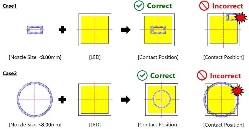
- The recommended location for tape removal is right next to where the pick and place nozzle picks up the led to prevent the led from tipping inside the tape bag and being damaged by the nozzle.
- Recommended nozzle height for pick-up operations is determined by the lamp bead manufacturer. Taking Nichia lamp beads as an example, After the LED is mounted onto solder paste on the PCB, the nozzle should further press the LED 0.2mm into the PCB.

Reflow soldering
Reflow soldering is one main processes in the SMT process which is important in lighting fixture manufacturing. Reflow soldering is mainly used to solder LEDs to the circuit board. It relies on heating to melt the solder paste so that the chip components (LEDs) and the circuit boards are fused and soldered together, and then the solder paste is cooled by reflow soldering to cool the components so that they are cured together.
Why is it called reflow soldering? Originally, the solder paste is mixed with some chemicals such as metal tin powder and flux, but the tin in it can be said to exist independently as small tin beads. After different temperatures, when the temperature is greater than 217 degrees Celsius, those small tin beads will melt. After being catalyzed by flux and other items, countless small particles will be integrated into one, that is to say, those small particles will return to the flowing state(Liquid state). This process is often referred to as reflux, which means that the tin powder returns to the liquid state from the previous solid state, and then returns to the solid state from the cooling zone.
Reflow profile
Reflow soldering is a key process in SMT production, and a reasonable temperature curve setting (ie, Reflow profile) is the key to ensuring the quality of reflow soldering. Improper temperature curve will cause welding defects such as incomplete welding, virtual welding, component warping, excessive solder balls, etc. on the PCB board, which will affect the product quality.
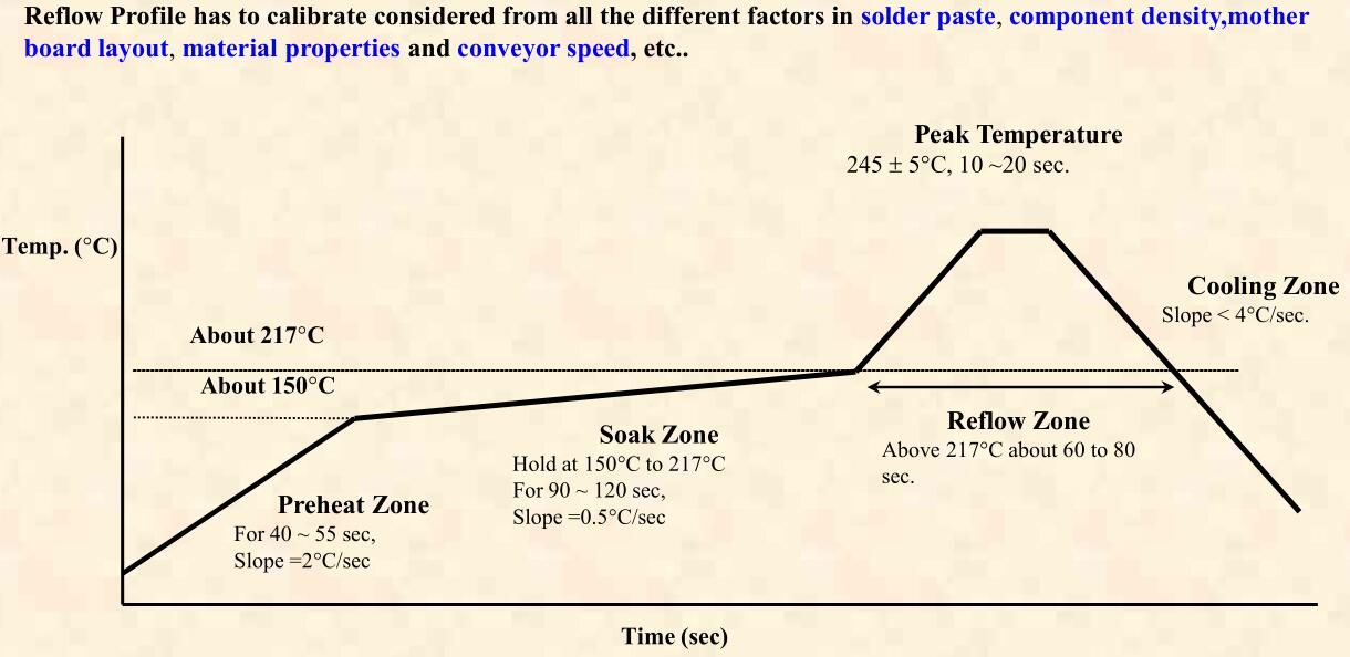
From the above figure, we can see that the furnace temperature curve is mainly divided into four parts. Preheat zone, active zone, reflow zone and cooling zone. The preheating zone mainly preheats the PCB and components to achieve a balance, and at the same time removes the moisture and solvent in the solder paste to prevent the solder paste from slumping and solder splashing. In the process, it is necessary to ensure that the temperature rise is relatively slow, so as to avoid the damage to the components caused by the rapid temperature rise. The active zone ensures that the solder is completely dry before reaching the reflow temperature, and also acts as flux activation to remove metal oxides from components, pads, and solder powder. The time is about 60~120 seconds (depending on the properties of the solder). In the reflow area, the solder in the solder paste starts to melt the gold powder, and it is in a flowing state again to replace the liquid flux to wet the pads and components for 60 to 90 seconds. The temperature of reflow soldering should be higher than the melting point temperature of solder paste, generally 20 degrees higher than the melting point temperature to ensure the quality of reflow soldering. In the cooling zone, the solder solidifies as the temperature decreases, so that the components and the solder paste form good electrical contact, and the cooling rate is required to be the same as the preheating rate.
Video of SMT machine
LED modules inspection
After the LED module is produced, we will install it on the lamp housing to adapt to the LED power supply. Usually a constant current LED driver will be used to drive the LED modules, ZGSM believes that a constant current driver is the best way to drive high power LEDs as it maintains a consistent brightness across all LEDs in-series. After the lamp is assembled, 24 hours of burn-in Time is necessary to detect the working state of the LED. At the same time, we will sample and test whether the light efficiency of the lamps meets the requirements, so that customers can ensure that customers get an excellent product.

Lighting fixture manufacturing
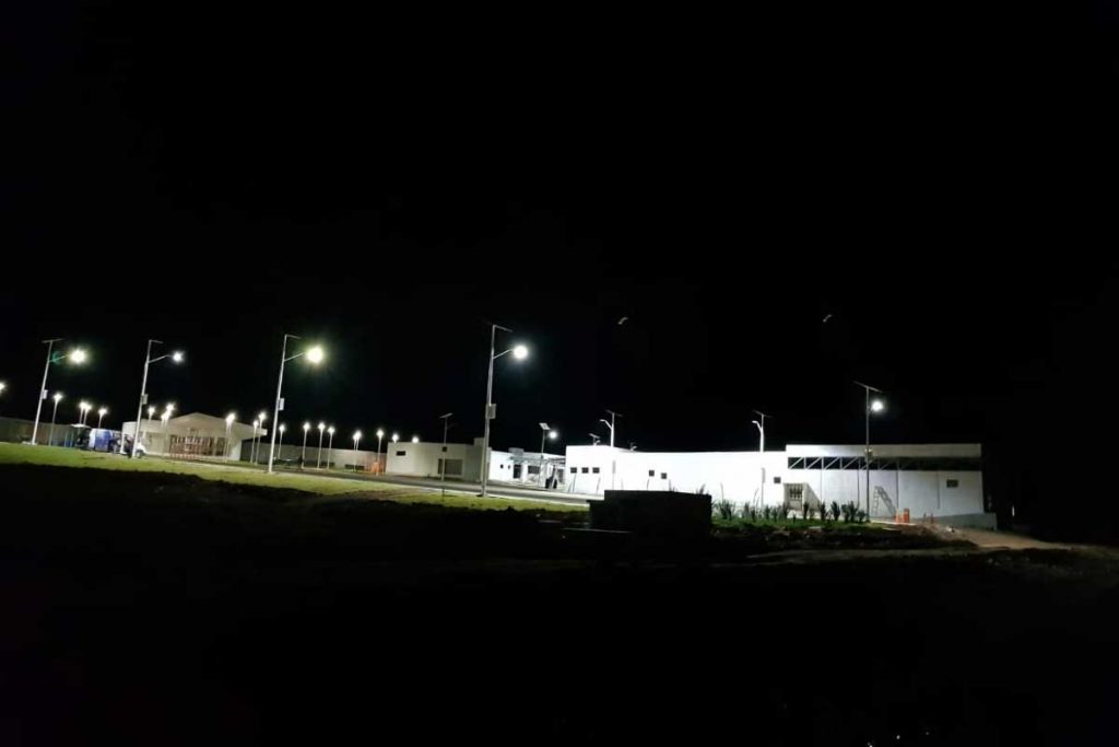
After the LED module is produced, we will install it on the lamp housing to adapt to the LED power supply. Usually a constant current LED driver will be used to drive the LED modules, ZGSM believes that a constant current driver is the best way to drive high power LEDs as it maintains a consistent brightness across all LEDs in-series. After the lamp is assembled, 24 hours of aging time is necessary to detect the working status of the LEDs. At the same time, we will sample and test whether the light efficiency of the lamps(below is the testing photo of street light) meets the requirements, so that we can ensure that customers get an excellent product.

Summary
Through this article, we hope that everyone has a certain understanding of LEDs, LED light efficiency, SMT process, LED module inspection, and lighting fixture manufacturing. ZGSM strictly follows the above process to produce LED street lights, flood lights, gas station lights, post top lights, highbay lights and solar street lights, etc., to ensure product quality. Based on the above production process, ZGSM dares to provide 5-10 years warranty for lamps. If you are interested in LED lighting products, whether it is indoor lighting or outdoor lighting, you are welcome to contact us at any time, ZGSM is dedicated to provide you with the best quality products and services.
Rated Products
Related Blogs
Related Cases
Rated Products
People also ask
Author introduction

Hello Customers,
My name is Taylor Gong, I’m the product manager of ZGSM Tech. I have been in the LED lights industry for more than 13 years. Good at lighting design, street light system configuration, and bidding technology support. Feel free to contact us. I’m happy to provide you with the best service and products.
Email: [email protected] | WhatsApp: +8615068758483

