DALI dimming and its application in indoor and outdoor lighting
DALI dimming and its application in indoor and outdoor lighting
Introduction
LED general lighting market in 2024 was affected by the downturn in demand in three major markets in Europe, the United States and China, the market value showed negative growth, the industry’s head lighting companies revenue fell as a whole. However, LED intelligent lighting and niche LED plant lighting market shows a counter trend growth trend. LED general lighting market is mainly by the stock market renovation to replace the demand for LED as well as LED high light quality, health and comfort lighting and intelligent lighting products to enhance the demand to drive the output value to return to positive growth. DALI dimming has been playing an important role in intelligent lighting. It was first developed since the early 1990s and has been officially used in the 21st century for its flexibility, scalability, energy efficiency ( Luminous efficacy of LEDs ), and ease of maintenance. This paper develops the basic concept of DALI, its working principle, and its application in indoor and outdoor lighting.
What’s DALI control?
DALI (Digital Addressable Lighting Interface) is a digital communication protocol for intelligent lighting designed for lighting control. DALI is not a single product. It is an industry-standard protocol that allows DALI-compliant components (ballasts, control systems, sensors, controllers, switches, etc.) from a variety of manufacturers to be seamlessly mixed and matched into complete systems. DALI allows users to precisely control luminaires via digital signals, including dimming, switching, scene setting, and more. The DALI protocol is open, flexible, and extensible. The DALI protocol is open, flexible and scalable, and is widely used in modern intelligent lighting systems.
What we need for DALI dimming?
DALI Dimming drivers are important actuator devices in the DALI system. LED drivers provide power to the light source and are usually connected directly to the lamp, as well as being important devices that receive control commands from the DALI dimming system. Each DALI luminaire has an individual address (0-63) through which the controller communicates with the luminaire. The fixtures can be connected directly to the DALI bus without the need for additional control wires. In addition to the DALI dimming LED driver ( What’s LED driver and how to choose it? ), the DALI protocol supports different control device types such as fluorescent ballasts and stand-alone emergency lighting control devices.
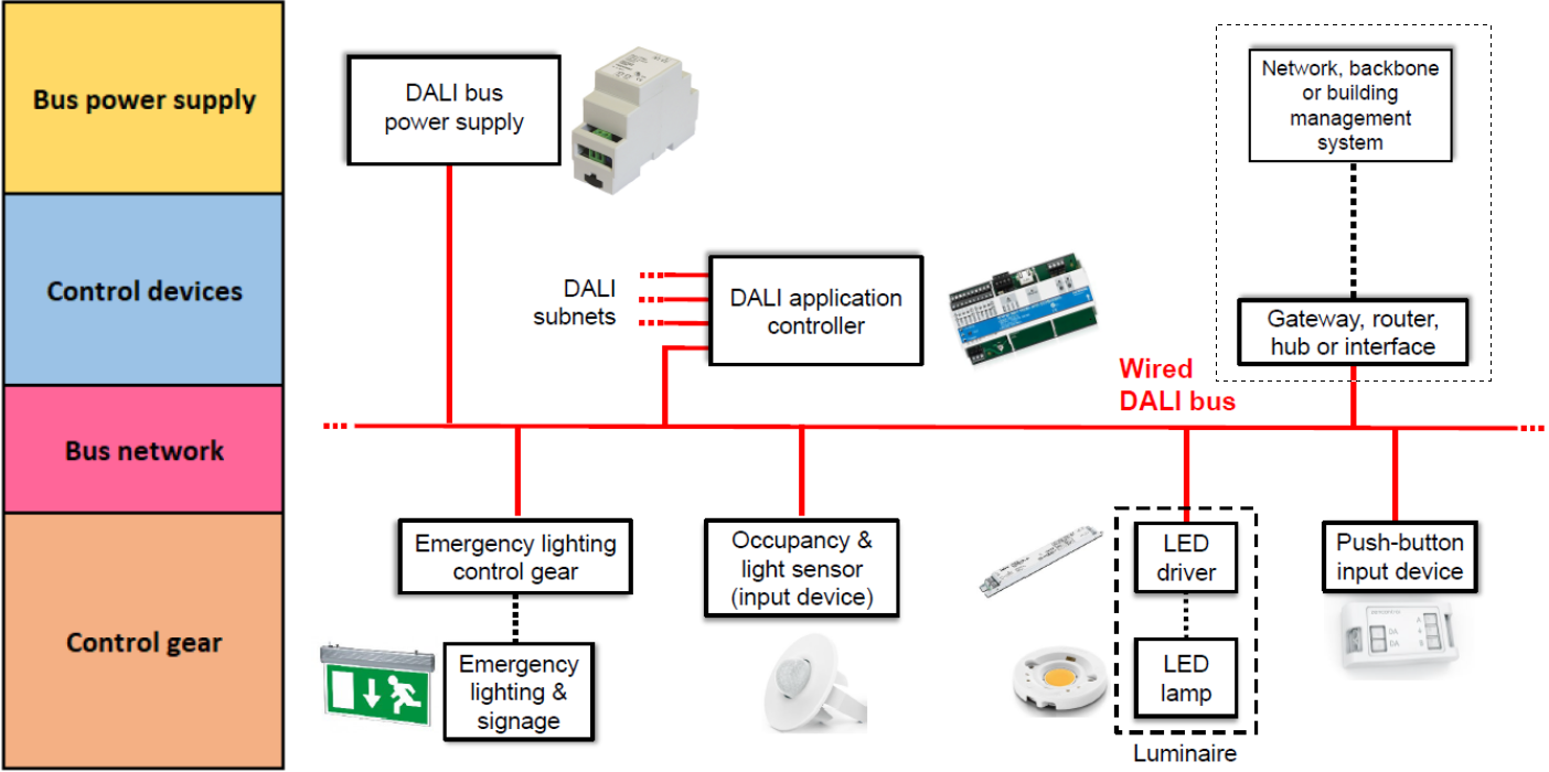
DALI bus
DALI bus is a pair of wires, which is the core of DALI. It carries digital control signals between input devices (such as sensors), LED lamps and application controller. It carries digital control signals between input devices (such as sensors), LED lamps and application controllers. It carries low-voltage signal wires, usually 2×1.5mm2, and a single DALI bus can connect up to 64 devices, including LED luminaires, panels, sensors and so on.
DALI power supply
The DALI power supply provides 16V communication voltage for the DALI bus. The power supply module inputs 220V AC power and outputs 16VDC to power the DALI bus. Its output current is <250mA. This component is always required in DALI system. It can exist independently or be integrated into the application controller. It maintains the bus voltage at the required level. The communication signal allows devices on the DALI bus (such as controllers, sensors, and lamps) to communicate bidirectionally.
DALI application controller
DALI controller which is also called application controller. It is the “brain” of the DALI system. They use information from control devices, input devices, other application controllers, external devices and applies the rules with which it has been programmed to generate outgoing signals to devices such as LED drivers. The application controller also manages the data traffic on the DALI bus, checks for conflicts and reissues commands if necessary.
DALI input devices
The input devices of the DALI system include various sensors and devices that support user input. Sensors include light sensors, occupancy sensors (Motion sensor and its application in street lighting ), etc., while the latter include various control panels, remote controls, scene controllers, etc. These devices can provide information from users and the environment to the DALI lighting control system. Finally, this information will be processed by the application controller and sent to the LED driver which used 24-bit data frames to achieve dimming, color and scene call control.
Other devices in DALI dimming system
The DALI system can basically run normally with the above devices. But when you need to control it through a computer, mobile phone, web page, etc., we also need some other supporting equipment such as computer (software), DALI USB, gateway or cloud server, etc. Through computers and mobile phones, we can realize functions such as address allocation, online monitoring, group setting, scene control, etc. The software system facilitates users to visualize operation and control. In addition, with the help of the DALI controller with built-in network, we can access the DALI host at any time through the mobile app to view the working status of the system in real time and control the devices in the system.
How do DALI dimming work?
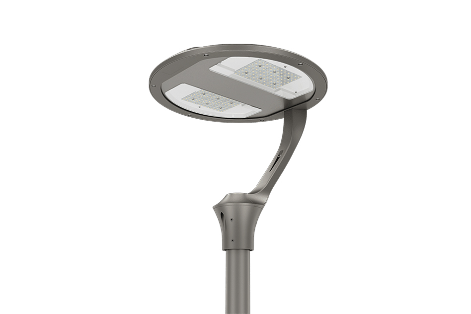
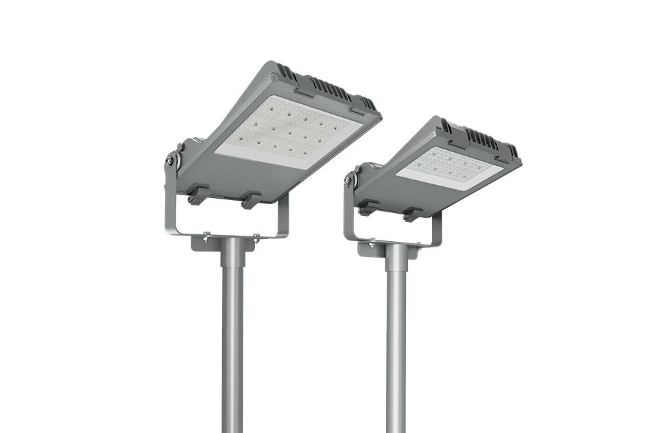
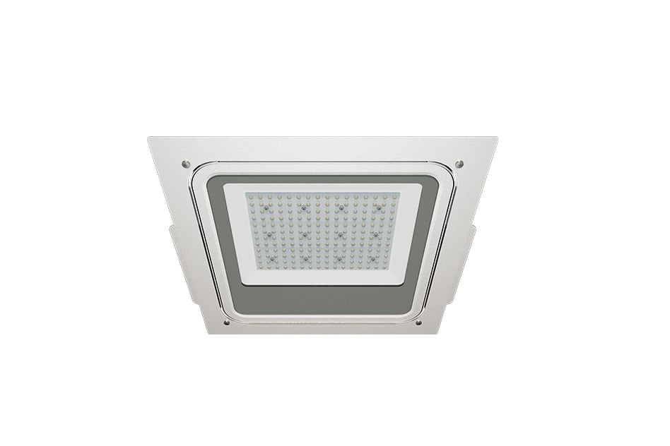
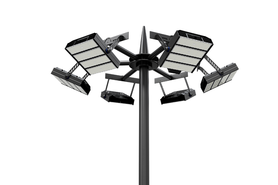
Through the knowledge of the previous section, we understand the main parts of the whole DALI system, they include luminaires, DALI power supply, DALI bus, DALI sensor/control panel, DALI controller, DALI gateway and software system, etc. DALI luminaires can be in various forms, which can be spotlight, panel light, canopy light, high bay light ( More about ZGSM high bay lights ) and outdoor lighting, etc. These luminaires can be built-in DALI dimming driver or external (which is rare at present). DALI luminaires come in many forms, from spotlights, panel lights, copy light, high bay light and outdoor lighting, etc. These luminaires can either have built-in DALI dimming drivers or external ones (which are rare at the moment). How do these components connect and communicate with each other to ensure the proper functioning of the entire DALI system? Next, we will start from the wire diagram and DALI system basic principles to expand the explanation.
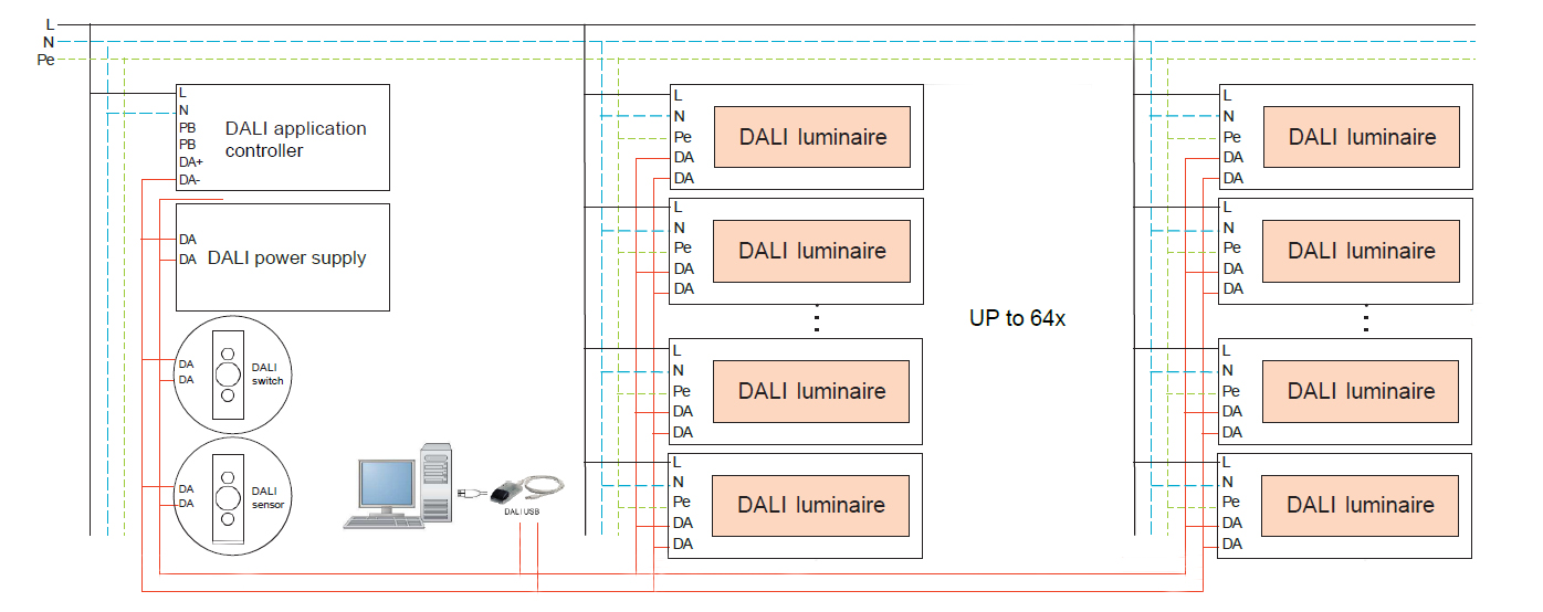
Wire diagram of DALI system
The following figure shows the basic wire diagram of the DALI system. We see from the diagram that the DALI system consists of application controller (with bus power supply) (≥ 1), DALI bus (1), input devices, LED fixtures ( More about ZGSM LED lighting fixtures ) with built-in DALI LED driver and computer. So how do they work? First, the bus power supply powers the interfaces of all the devices on the bus to ensure that they work properly. The control devices (including application controllers and input devices) send query, dimming and switching commands over the bus, which are received by the LED fixtures and executed accordingly. For example, if we need the operating status of a luminaire now, we can send a query command through the control device(application controller), and the LED luminaire will return status information including current brightness and fault information, etc. This is often a relatively simple single-master architecture, i.e., there is only one control device. When the system has more than one control device (e.g. the light sensor detects that the ambient light is getting brighter and sends a dimming command ( What’s 0-10V dimming? ), and the user sends a shutdown command through the application controller), the system adopts a multi-master architecture, and at this time, the system needs to decide which command to execute based on the priority or the time slice in order to avoid conflicts.
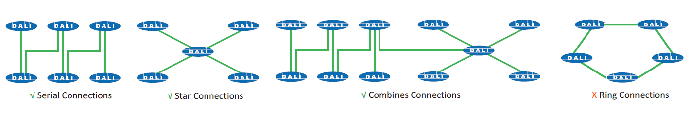
Connection methods of different devices in the DALI system
In a DALI (Digital Addressable Lighting Interface) system, the way in which the devices (LED luminaires and input devices) are connected is critical to the stability and functionality of the system. Series networks, star networks and combined networks are possible, whereas loop(ring) networks and fully connected networks are not permitted in DALI systems. Series connection networks are relatively simple and material-efficient, and are suitable for small systems. Since the DALI bus requires a length of no more than 300 meters, the whole system will be smaller, and the failure of one device will affect the communication of the subsequent devices, while the Star connection sets up a separate connection line for each device, and the application controller is connected to each device separately, so that the failure of one device will not affect the communication of other devices. Combined network is a combination of series network and star network, which takes into account the cost and stability of the system, so the wiring is relatively complex. Below is a diagram of several connection methods.
DALI control in indoor lighting
DALI systems are widely used in the indoor lighting field, with common applications including offices, shopping malls, hotels, hospitals, schools, workshop ( LED lighting in workshop and warehouse ) , and homes. The DALI system enables dimming, grouping and scene setting to enhance the user experience and save energy. The system also meets the individual lighting needs of different areas, such as meeting rooms, lounge areas, corridors and other specific spaces. When used in conjunction with various sensors (e.g. motion sensors, light sensors), the DALI system can automatically dim the lights to further improve energy efficiency. When paired with a variety of control panels, users can not only manually adjust the brightness of the lights, but also centralize the control of all the lights in a certain area, or control a particular light individually. When working with a remote controller, users can realize flexible remote control, quickly adjusting the brightness and working mode of the lights by pressing the buttons. In addition, the DALI system simplifies the maintenance and management of luminaires, such as fault detection and status monitoring.
DALI control in outdoor lighting
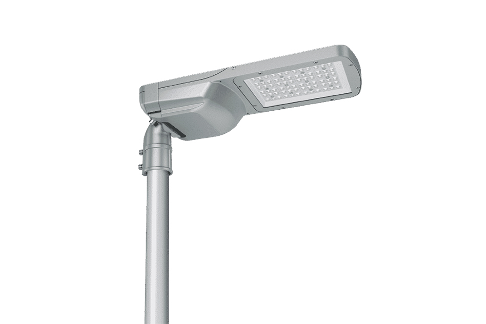
The application of DALI system in road lighting is more using DALI dimming protocol. Common application is Zigbee and LoRAWAN wireless control system with DALI driver LED lamps and lanterns used together, the user can be through the platform to send commands to the gateway, the gateway carries the launch of Zigbee or LoRa signals (two mainstream types) to the light controller, and the lighting controller will convert the signal into DALI signal and send it to the LED driver to finally realize the dimming, switching and status monitoring of the lamps. We often hear 0/1-10V dimming, in fact, LED lamps equipped with DALI driver can also be dimmed by DALI dimming to switch on and off the LED lights. The main difference between the two is that 1-10V dimming using an analog system, while DALI dimming using a digital system. Because of this, in recent years DIIA has introduced the D4i standard, which is a continuation of DALI-2. The core of the D4i standard ( What’s D4i? ) is to provide more data support and IoT (Internet of Things) integration capabilities for intelligent lighting systems (especially LED luminaires). D4i which means DALI for IoT, it also enables DALI inside intelligent, IoT-ready luminaires. it provides data collection of energy consumption, temperature, faults, and light output for the entire system ( Why we shall pay attention to light output degradation? ). The D4i also simplifies the process of adding sensors and communication devices to the luminaire, and when combined with connector systems such as Zhaga Books 18&20 or NEMA/ANSI C136.41socket ( NEMA vs Zhaga , What is a NEMA enclosure? ), the D4i enables plug-and-play interoperability to facilitate the addition of various sensors and communication devices to the luminaire.
ZGSM lighting solution
ZGSM is a manufacturer specializing in the production of various high-quality lamps, including street lamps, highbay lamps, floodlights, stadium lamps ( ZGSM high mast lights for stadium lighting, View LED outdoor stadium lighting supplier ), and gas station lamps. We are committed to providing customers with efficient, energy-saving, and intelligent lighting solutions. In order to meet the needs of modern intelligent lighting, we have equipped these lamps with advanced DALI drivers to ensure that the lamps can be seamlessly integrated into the intelligent lighting system. For example, LED industrial lamps can be equipped with drivers that comply with the DALI-2 standard, providing more precise dimming control and higher energy efficiency. Street lamps can be equipped with D4i drivers+Zhaga socket, which support remote control, data collection and monitoring functions, helping customers achieve more efficient energy management and maintenance. If you are interested in these products, please contact us.
Summary
This article provides a comprehensive overview of DALI (Digital Addressable Lighting Interface) control and its applications in indoor and outdoor lighting ( Click the link to explore the top LED lighting manufacturer in China and find the perfect lighting solution for your needs! ). It begins with an introduction to DALI technology, i.e., what DALI is. It also lets us know the basic components required to implement a DALI control system, and how DALI control operates, including communication between different devices. A detailed circuit diagram of a DALI system is provided to illustrate its structure and functionality. Finally, it showcases ZGSM’s innovative lighting solutions using DALI technology, highlighting how ZGSM uses DALI to provide intelligent ( Smart lighting control for street lights ) , reliable, and energy-efficient lighting systems to meet different needs. Whether it is a residential, commercial, or industrial environment, this article can help users understand and utilize DALI dimming for lighting management.
Related Products


Related Blogs


Related Cases


People also ask
Author introduction

Hello Customers,
My name is Taylor Gong, I’m the product manager of ZGSM Tech. I have been in the LED lights industry for more than 13 years. Good at lighting design, street light system configuration, and bidding technology support. Feel free to contact us. I’m happy to provide you with the best service and products.
Email: [email protected] | WhatsApp: +8615068758483